
Technical
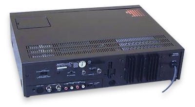 Black SL-C9ES rear |
Camera SocketThe 14 Pin Camera socket is known as a Sony K-connector. Details of the pin connections are available online.Multi-ConnectorThe 8-pin Din Connector is known as a Sony Multi-connector and carries a combined Audio, Video and Remote control (later known as CTRL-S) signals. Details of the pin connections are available online. |
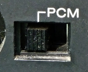 PCM switch |
PCM SwitchMake sure that under normal usage that the PCM switch on the rear of the unit is switched off. When switched on, the drop out compensator circuit is switched off, this is to allow the error correction on a PCM recording (using a PCM-701ES or similar) to operating more effectively. The result on a normal recording will be more visible drop outs. See also PCM.Additional remote control functionsAlthough not available using the supplied remote control handset it is possible to operate eject mode via a remote control. This code can be found on some modern universal remote controls such as the One for All. In addition one of the channel advance functions of the SL-F1 remote works on the C9. |
Fault and repair guide |
|
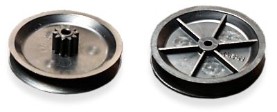
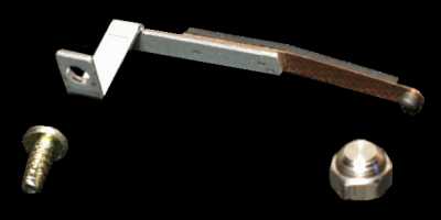
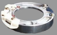 Upper drum |
Irregular tape transport during rewind/review.This is caused by the tape which tends to stick to a worn upper drum. It can be fixed by replacing the upper drum. Sony now supply an improved type which is made of a harder wearing alloy.The picture opposite shows the new upper drum which no longer has a mounting plate. |
 Broken gears on the carriage causing noisy loading |
Defective loadingThe plastic gear on the cassette carriage often breaks. This usually leaves the tape trapped in the machine and if tape eject is attempted it can result in more broken parts (such as the inner and outer cassette flaps). Sony supply a 'carriage modification kit' which contains an improved set of gears and unlike the original are made of metal as opposed to plastic.To fit this kit the carriage must be removed from the deck. This can be a tricky job because the front panel must be removed first. If you attempt this task then pay special attention to the rod which connects to the bottom of the carriage before removal. Dec 1997: The kit is no longer available from Sony. The picture shows a complete carriage. The two circled areas show the location of the loading gears at each end of the metal rod. |
 Updated threading gear (no metal bush) |
Grating noise during tape threading/unthreadingThis is caused by a split threading/pulley gear. Repair is by replacement. It advisable to replace the threading belt at the same time.The original version had a metal bush in the centre that caused the surrounding plastic to crack, probably as a result of thermal expansion/contraction over a long time.
|
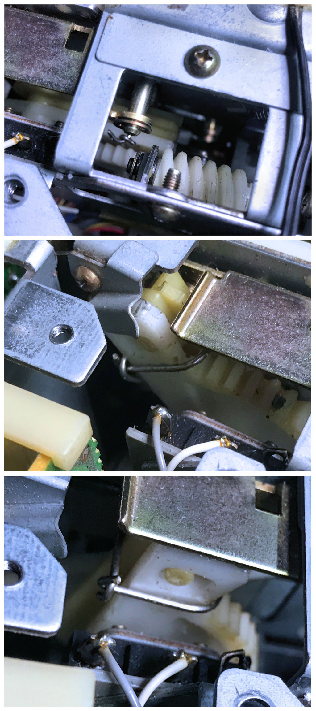
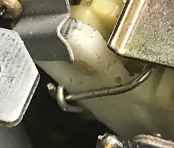 Side loading gear fix |
Side loading gearA fairly common fault on the SL-C9 involves the right hand side gear popping off (over) the pin on the lever it pulls and pushes whilst loading (possibly as a result of a tape being forced in whilst loading).Repairs sometime involve adding a small screw and washer to stop this happening, but in time with the plastic hardening, the screw ends up breaking that pin. An alternative simple fix is to use a paper-clip squared off to form a
loop (with the ends "holding hands") around both levers. This still allows the levers slight movement
for the pin in the slot which they need by design, but does not foul other parts of the mechanism in use.
Thanks go to Noel Higgins for this fix |
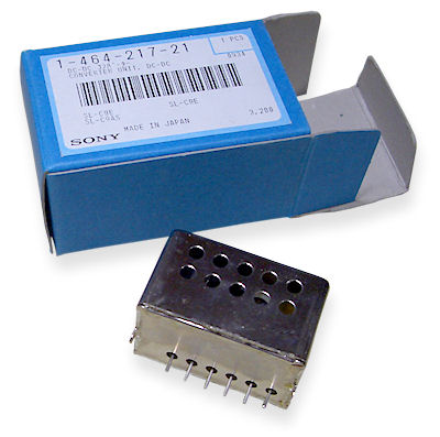 MKII DC to DC converter See also the parts page |
No fluorescent displayThis is caused by failure of the DC to DC converter in the power supply. This is a sealed unit which is extremely difficult to open and can seldom be repaired if successfully opened. Sony supply an improved replacement which can be identified by the air holes along the sides. The original unit was completely sealed.It has been known for these replacement units to fail after a few years operation. However, unlike the original ones they can usually be repaired by replacing the reservoir electrolytic capacitors inside. The DC to DC converter also supplies the tuning voltage hence when it fails no channels can be received. Dec 1997: The DC to DC is no longer available from Sony. Take a look at the DC to DC converter page for full information on fixing the unit. Including circuit diagrams. Reel spools running continuously.This can occur when one of the reel motor mute transistor fails. |
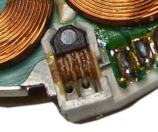 Hall effect sensor attached with glue |
No head drum rotationYou may find that the head drum fails to rotate. This is due to a problem with the Hall effect device on the head drum motor which is secured by a blob of glue. Full details on how to fix this can be found on the head motor page. |
 Pinch roller |
Pinch RollerOver time, the pinch roller surface will become polished which can reduce its ability to pull the tape through correctly. It is recommended to clean or replace this.See also: Parts - Pinch Roller for information on how to fix this. |
 Earth grounding kit |
White static noiseSony produced a grounding kit to help with the problem of static build up on the head. |
Quick fault guide
Please click on the button if you are able to contribute a solution to this list or would like to add to, or update PALsite's information on this model. Please note, questions will be removed.If you have a question about this model, please raise it on the chatpage.
| Fault | Solution |
|---|---|
| Blank unmodulated raster on playback of own recordings | Clean or replace the audio/control track head |
| Capstan running fast in playback and record | Check IC006 for failure |
| Capstan running slow | Check IC002 on the SS11 board for failure |
| Chewing tapes | Check the condition and positioning of the pinch roller |
| Clock incorrect and flickers during recording | Check IC601 on panel SS11 for failure. |
| Colour patterning on picture | Check IC605 on panel SS11 for failure |
| Eject LED flashing at switch on then goes into standby | Suspect excessive friction in the front loading mechanism |
| Intermittently ejects tape | Check transistor Q633 for failure |
| Intermittent loss of display when warm | Check for failure of IC201 on the TM31 panel |
| Intermittent loss of e-e picture | Check filter SF001 on tuner panel for thermal failure |
| No or incorrect colour in playback | Check resistor R114 for failure |
| No or loss of picture, no colour during playback | Check capacitor C38 on the RV7 board for failure |
| No capstan motor rotation | Check fusible resistor R530 (0.2 ohm on SS-11 board) for open circuit. Replace it with an electronic fuse (Sony part: |
| No picture during playback of colour recordings | Check for failure of IC005 on the RV7 panel |
| No remote control operation | Check capacitors C203 and C204, if OK then check IC201 |
| No sound in playback or e-e | Check diode D515 on panel AM1 for failure |
| No tape remaining indicator | Check IC501 on panel JR for failure. |
| Permanent drum rotation | Check resistor R329 on panel SS11 for failure. |
| Poor or low sound, back tension setting and audio head ok | Check for correct operation of op amp chip IC520 (UPC14581) then check switching chip IC521. |
| Poor or noisy pictures | Clean the tape path then check the setting of tape guide no. 5. If OK check for dry joints around transistor Q701. |
| Self switching to other functions, LED's flashing at random | Check IC601 on the SS11 panel for failure |
| Stops after few seconds, no tape take up | Check fuse F001 on the SS11 panel for open circuit. |
| Will not load tape, eject LED flashing | Check the unload end switch for poor contacts failure. |
| Will not switch on | Check capacitors C203 and C204 if OK then check IC201 for failure. |
| No power up. Front panel LEDs not alight | Check mains switch at rear of unit is set to on. |
| Cannot load tape | If you can`t physically get a tape into the slot more than half way (i.e. past the guides above the tape visible when cover is off) These are two small pieces of silver metal with a black rubber band round them either side of the carriage - One of these may have dropped lower than the other, preventing a tape being inserted.
I have seen 2 C9s like this. In this case, get a finger round the back and push this guide up as you insert a tape. The motor will try to take it after the tape has gone under the guide. Push the tape in with adequate force, but don`t push too hard. If you get it right, the tape will load and thread up normally. Then, look directly below the 3rd tooth of the "L" shaped plastic gear which is mounted on the side of the carriage, you will see a small metal lug in the same place on each side of the carriage. This lug should point 90 degrees into the carriage. One of them will be bent, probably to only a 45 degree angle. Use a flat screwdriver or similar to bend it back to 90 degrees. When you are happy both lugs match each other, eject the tape normally. The vcr should now load tapes normally. |
| Split threading gear | If you have a split threading gear (grating sound when threading and unthreading) it needs to be replaced. Undo the two screws holding the haed amp can, then lift it over on its hinges. The split gear is the larger of the two black pulleys you see with a band between them. Lift the band off the large pulley and then use a small screwdriver to lift the o ring off the top of this pulley. The pulley will now lift easily off. Replace making sure the teeth of the two gears mesh. Refit the o ring and refit the band. |
| That clunky, twangy sound on rewind/f.fwd | Don't panic! You probably don't need a new upper drum ass'y. I used to work on these machines when they first appeared on the UK market and even then, (often under warranty) we used to get quite a few C9/F1's with this fault! (The other common one was dried up electrolytics in the PSU). I was an apprentice at the time, and my "boss" showed me this simple fix which I never forgot; thoroughly 'scrub' the upper drum with an ink rubber, yes, an ink rubber! Preferably, one of those that looks like a white 'pencil'. It works, honest! Obviously avoid the heads; I am still running a C9 today (something you can hardly lift has got to be good). Have fun! [email me: [email protected]] |
| No freeze-frame advance or 1/10th speed, but 1/5th OK | If freeze frame forward/back and 1/10th speed do not work reliably or at all, even though 1/5th works, a slight anticlockwise adjustment of RV017 on the JR-1 board (underneath the tuner panel) should fix it. |
| Muffled audio, may be intermittent | Muffled sound on good recordings, which may be momentarily overcome by applying gentle pressure to the top edge of the tape as it leaves the audio/control head, is of course usually caused by audio head wear (even if the heads look perfect). Head alignment is the other possibility but should be right unless someone has been twiddling.
Replacement of the A/C head is a fairly major undertaking because the cables weave all over the shop. Remove the loading motor to gain access to the cable run beside it. Though the cables are routed along with the erase head cable, the latter is not connected in any way and its cables can be refitted after A/C head cables have been installed. Both bottom panels need to be swung out to gain access to connectors because the control head cable goes one way (through cable ties too) and the stereo audio cables go another. The A/C head assembly all comes off with just the two screws on the top plate (one has a black earthing wire with it). Care not to misplace the shims under the top plate. Little or no A/C head alignment should be necessary after replacement. |
| Cassette loads but won`t thread | Either it is the threading motor which is faulty, or possibly the metal bar which connects to the bottom of the cassette bay from the right hand side of the carriage could be bent. This bar could have got bent if the carriage has been replaced at some point. Remove the carriage and check that the two parts of this bar are not bent. If so, straighten them and reassemble. |
| Sony BETA'S! (the best?) | After reading all that I now know WHY I prefer the Sanyo's.
Talk about problematic. Still it's nice to think someone has gone to all that trouble with these solutions. |
| They wear out and are very complicated so more things to go wrong | Keep repairing them they are worth it. Sanyos might last longer but the joy of using an SLC9 makes them so much fun to have. The Sanyo M30 has slow motion but nothing like the Sony which does it in both directions and has APC and real time counter to boot. |
| Clock and tuner data lost, problems powering up | Yellow RAM battery BA-301 on the TU-35 board has gone bad. Replace with a 2.4V 90mAh (or more mAh's) NiCd or NiMh cell. |
| Stops in rewind or fast forwards after a few second. Drum is spinning | This is the capacitors driving the take up and supply spool osc sensors. on board SS-11 replace cp0005, cp033 ten any electrolytics in the triangle between IC003 and IC002 and IC610. lots of 1uf 50v and 10uf 50v |
| Stops after few seconds and capstan ran too fast | Changed ss-11 board and replaced battery 2,4v with accu-batteries. |
| Little lose tracking & little white noise in picture and sound | Easy, just clean all cassette department using alcohol 95% and grease in takeup reel and feed reel parts. |
| The picture is clear put not stable | It is probably a warn tension arm. Replace the arm only and spring. I change only the round steel in arm with another from an audio cassette player, now it is good. |
| Noisy rewind or forward and search and tape a little stuck on drum head | Remove the upper drum and anodize it using polish liquid (same material for polishing car) but for aluminium using cotton then clean it than dry it in hot air. After fix, replace it in vcr and enjoy. I do the same in lower drum too, but take care to avoid head tips. |
| DC-DC converter repair (no display fault) | I've done a YouTube video showing repair of a MKII converter module: https://www.youtube.com/watch?v=_9CVPghyCcY |
| Tape transport stops - head and spool motors run fast | Pressing any transport functions result in the machine stopping after a second or two. The heads are heard to spin too fast and the spool motors run fast with no capstan motor movement at all. The fix was to replace the glass 20mm 500Ma slow - blow fuse on the RV7 board. |
| Sync problems or lines in video output (BNC) | 1000uF 10V capacitor bad in video output circuit, bottom PCB behind the BNC connectors. Replace with low-noise or low-esr type. |
| No Audio Output | Check position of RF test signal switch! If switched ON it kills the RCA Audio output. |
| Front loading motor and pinch roller solenoid appear dead | Heads, capstan and reel motors all operate fine. Check the T3.15A fuse on board SS-11, F603 which is located near the large 2200uF capacitor. |
| Cassette Wont eject | Check Q622 (2SC2785) Syscon |
| No power | Dead-3.15A fuse blown. Check D601 (Bridge Rectifier) s/c on Mains input panel. |
| Split threading gear | On both my C9's, the brass bush is in two parts, one third in the wheel, and two thirds in the spindle/small cog. Removing the longer bush from the small cog allows the split to close, or to be superglued (careful not to clog the teeth) and the threading gear rotates and meshes again quite happily. Hope this helps someone. Keith. |
| No line sound output on either channel 1 or 2 | Tests on IC522 on AM-1 board showed all normal except pin 4 which was 1.54V instead of 8.4V. R671 high resistance at 2K Ohms when should be 33 Ohms. Replacement cured problem. Note this fusible resistor is a safety critical component. |