 |
|
|
|
The Definitive Betamax Web Resource
|
||
|
|
|
|
The Definitive Betamax Web Resource
|
||
Similar designs are present in all later Sony Betamax models. Models such as the SL-C7 and before use a slightly different drum and other manufacturers also use their own designs.
All models will produce poor pictures when the video head wears out. Of course poor pictures will also be produced at any time during the life of the head if the head tips become clogged. Head wear is noticeable by observing streaking between sharp dark to light or light to dark transitions (i.e. high frequency components of the picture). These symptoms appear first on new recordings made on the same machine as opposed to play back of pre-recorded material.
For hi-fi models, wear on the video heads goes hand in hand with wear on the hi-fi audio heads causing bad hi-fi audio.
(See also head cleaning guide).
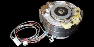
If you suspect that the problem is due to a worn upper drum, then you will preferably need to replace the upper drum. This is normally a fairly straight forward task but must be performed with precision to avoid damaging the delicate video head tips. The upper drum is held by a single bolt from the side and is removed using the appropriate Allen key. For hi-fi models, the task is more complicated because of the HiFi transformer assembly which sits on top of the drum as you see it from above. Another notable exception is the SL-C9 / SL-F1 where a brass plate is also used to secure the upper drum. This plate is easily removed.
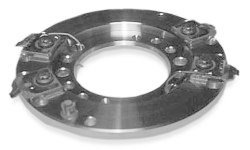
This complete unit can be replaced, although care should be taken to ensure that there is correct clearance (0.3mm to 0.6mm) between the shield and the rotor of the head motor when replacing. This is achieved by using a set of thickness gauges.