 |
|
|
|
The Definitive Betamax Web Resource
|
||
|
|
|
|
The Definitive Betamax Web Resource
|
||
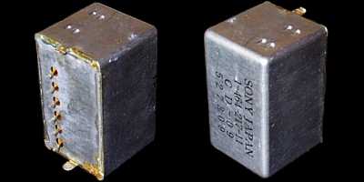
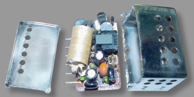
Components that fail most often are Q1, Q2, C1, C2, C3, C4 and C5. Most of the work needed is in getting the can open in the first place. A lot of heat is necessary because the can acts like a heat sink.
Q2 is listed in the diagram as a 2SD774. Normally though the unit uses a 2SD789, which are often harder to replace. Q2 is often the first component to fail.
Note: the circuit diagram shown actually contains a few typos. Namely the components shown are not those found in the actual unit. See below for how the Mark II version improved on this original design (and where the typos were).
Thanks also to Noel Higgins for some extra information
Terry Magee has kindly provided some very detailed information on his successful Mk1 DC to DC repair. Additional circuit diagrams are also included. Full repair account.
Fixing a dim display - by Neil Boyd
I recently bought a C9 but the fluorescent display was very dim and couldn't be seen with the front fascia fitted. I removed the converter and with the help of Terry's guide replaced capacitors and transistors with good units. The A.C output was measured at 10.5V.
When I replaced the converter it was still the same, dim display, though everything else worked. I then took out the select on test resistor R8 and measured it to be 30K as marked. A variable resistor was then tried and at any value over 30K the circuit went into saturation and distorted the AC waveform. I then replaced R8 with a new 30K resistor( actual measurement 28K), and measured the A.C. again which was now at 11v, refitted the converter which then worked perfectly, with a bright display.
The 11V A.C. supply therefore controls the fluorescent display brightness, and the choice of R8 can be critical.
Fixing the display on a Sony SL-C9 Betamax video recorder (DC-DC converter repair) - by Colin McCormick
Dim or no display is a common problem on the Sony SL-C9 Betamax video recorder, and is due to failure of the DC-DC converter module. Here we repair one which has intermittent operation.
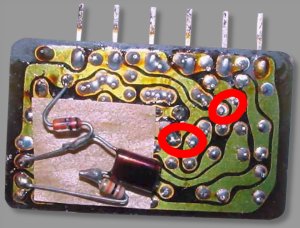
The Mark II version (which is also now discontinued) also had its faults. The unit tended to suffer from dried out capacitors and dry joints. The picture shows two particular areas to look out for. When this unit fails, replacement of C4 and C5 is usually all that is necessary.
The Mark II changes the value of C2 and adds a resistor, capacitor and diode around Q2. See MKI vs MKII PDF for full details of the differences.
Thanks go to John Rowing for supplying the pictures and Andrew Finch for the PDF circuit information.