Description
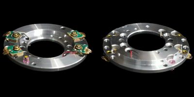
This is the head disk assembly for an
SLO-1700.
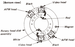
It consists of 4 head tips mounted on an assembly (2 video and 2 Hi-Fi).
N.B. NTSC systems combine the Hi-Fi and video onto the same head pair.
When mounted in the
complete drum, each head tip protrudes through a gap between
the upper and lower drums.
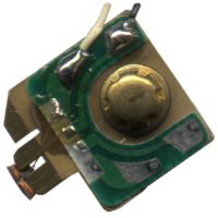
Head tip
The heads are extremely delicate and comprise of two small
coils with a very small gap between them. These two small coils can be
seen above in the bottom left of the picture.
See also Complete Drum Assembly and
Upper Drum.
Symptoms
There are a number of different symptoms associated with heads.

Normal picture

One head clogged
If one head is clogged or damaged, it can sometimes give a similar
effect to that seen when the tracking is not correctly set. e.g. A
large amount of snow/lines on the picture but usually the bottom of
the picture remains perfect.

All heads clogged
If both of the heads become clogged, then the whole picture becomes
severely degraded. Although this looks like the worst case, it is the
one which is most likely to be solved by cleaning the heads.
If the Hi-Fi head(s) are clogged or damaged, then Hi-Fi sound is
either completely lost (linear audio only can be heard and the Hi-Fi
light is no longer lit) or a 'clicking' type sound can be heard.
If all the heads are worn then white lines are seen on the picture
and areas of the picture containing sharp contrast often bleed with
black. e.g. If a dark object is placed in front of a white background,
the right hand side of the dark object 'bleeds' into the white.

All heads worn
See also the Head Cleaning Guide.
Fixing
The first step in fixing the heads is to give them a clean. Follow the detailed
instructions in the
Head Cleaning Guide. If this
fails to improve matters then they might need replacement.
An easy test to see if the heads are beginning to wear out is to test
a pre-recorded tape in the machine. If this plays well in the machine but a
recent test recording made on the same machine has white lines on it, then
the heads could be worn.
The Maintenance Guide states that the
heads and upper drum should be replaced after every 2000 hours of use.
Replacing
Accessories: adjusting jig, feeler gauge 1, feeler guage 2.
Note: Keep them after replacing the rotary head disk, since they will be needed when replacing the guide arm assembly and the rotary coupler assembly. (They are not delivered with the guide arm assembly or the rotary coupler assembly).
- Removing rotary head disk assembly
- Unscrew two screws (1) clamping the damper assembly, and remove the damper assembly.
- Unscrew hex socket head bolt (2) with an Allen key.
- Unscrew two screws (3), and remove the upper drum assembly.
Note: Remove while turning the upper drum assembly, taking care not to move the adjust plate. If the adjust plate is moved, the tape path is influenced.
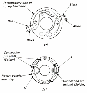
- Unsolder the 4 connection pins (4) from the coupler disk.
- Unscrew 2 hex socket head bolts (5) and remove the rotary coupler assembly.
Note: To be able to refit the rotary coupler in the correct relative position, memorize the position relative to the connection pins (4).
- Unsolder the red, white and black leads at four positions from the intermediary disk of the rotary head disk.
- Unscrew four hex socket head bolts (7), and remove the rotary head disk assembly.
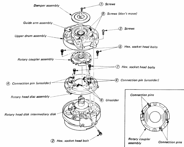
How to remove rotary head disk (1)
How to remove rotary head disk (2)
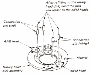
- Refitting rotary head disk assembly
Note: Be extremely careful not to damage the head chip by touching or fouling it.
- Solder the four leads to the video head of the rotary head disk assembly. (Caution on correct orientation of the magnet.) Thread the leads through the holes.
- Refit the four connection pins to the rotary head disk assembly.
- Bend the connection pins and solder them to the AFM heads.
- Refit the rotary head disk assembly, paying attention to the positions of the red, white and black leads, and to the orientation of the connections pins. (White in Ach side)
- Tighten four hex socket head bolts (7) and solder the leads to the head intermediary disk.
- Refit the rotary coupler assembly, and tighten two hex socket head bolts.
Note: Align A-a and B-b between the rotary head intermediary disk of the rotary head and the rotary coupler assembly.
- Solder the four connection pins to the rotary coupler assembly.
- Refit the upper drum assembly without moving the adjust plate, and lightly tighten screws (3). Tighten hex socket head bolt (2) and then tighten screw (3) firmly.
Note: While refitting the upper drum assembly, take care not to foul the head chip.
- Check the AFM rotary transformer gap with the feeler guages. Feeler 1 must go in and feeler 2 must not go in. If the gap is incorrect, readjust the gap.
- Refit the damper assembly, and tighten screws (1).
How to refit rotary head disk (1)
How to refit rotary head disk (2)
How to refit rotary head disk (3)
Thanks to Mark Perry for supplying this information